Gedi

New Member
Jan 4, 2025
3
2
3
Victoria
Hi All, my first post! :) I have a 2017 Jayco Starcraft Pop-top and I am currently using my old Falcon RTV ute to tow it (upgraded to a 2300kg towbar). I found an older copy of the Jayco 12 pin "tow vehicle wiring instructions" (how to wire the trailer socket on the tow vehicle). This came with my van.

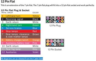
The guide talks about using pin 2 and 3, on the socket, to provide auxiliary power (a 20A circuit) to charge the van battery (via the BMPRO J35 BMS) and pins 9 and 10 (a 30A circuit) to run the fridge whilst towing.

The original wiring in my RTV trailer socket already has a 30A circuit for pins 9 and 10. Pin 9 is +12v connected directly to the battery, via a couple of circuit breakers, (always live). Pin 10 is earthed to the "Right Centre Ground" on the ute, however the Jayco documentation says "Connect directly to vehicle battery negative terminal". The Aux battery charging circuit, where pin 3 is the Ground, says "Connect to vehicle chassis ground point. Do not connect to trailer harness ground wire. Do not connect directly to negative battery terminal". (The original wiring on my ute has pin 3 and pin 10 connected together in the trailer socket harness and then one thick wire running to the "Right Center Ground"/ chassis earth.

My questions are:
1/ given that the battery negative is connected to the chassis earth anyway, what is the difference? What possible damage could I do/ disadvantage is there, for connecting the fridge circuit back to the tow vehicle chassis rather than the battery negative?
2/ Conversely why does the 20A charging circuit use the chassis earth rather than the battery negative?

I am hoping there is someone smarter than me out there! All info appreciated.

Cheers
Gedi4
 

jazzeddie1234

Well-Known Member
May 19, 2016
641
783
93
Mandurah
A few ideas....although someone may have the exact reason

First the fridge 12v high current wiring is not usually connected to anything in the caravan. Both the pos and neg run direct from the fridge to the 12 pin so connecting an earth anywhere else won't work. In the car it is good practice to continue this pos and neg all the way to the cranking battery (via a relay or whatever) because the current draws are so high and you don't want any voltage drop if at all possible.

Second the negative of the caravan batteries are usually connected via a shunt ( a device used to monitor the current draw on the batteries) so a direct connection to a caravan battery negative will bypass this.

Third, If you have a setec battery charger in the van the 20A pos and neg (now I am talking about the 7 pin strip) connects directly to the AUX input on the back. Various other circuits connect to the negative wire, but not via the chassis. I think the chassis may have a ground wire but it's not really a good connection.

Hope someone else can fix anything I said wrong
 

Drover

Well-Known Member
Nov 7, 2013
12,938
19,701
113
QLD
Connecting to chassis ground nearest the battery is nowadays the ideal place due to modern vehicle wiring set ups but direct to aux battery is usually fine ...................

I follow the Narva 7/12 pin guide which is the standard layout, saves a lot of work in the long run, as the wiring plan is printed inside the covers................................ I would firstly use a meter on the pins to confirm what each one actually does or cross check the wiring code at each end, often a Vans wiring won't follow a printout or changes have been made along the way .................

It isn't unheard of that the van will be using pins 2/3 for battery charging that way if someone goes to using a 7 pin no changes needed but using 8/9 for fridge is normal, many actually just drop the fridge circuit and run a dedicated 6 or 8B&S cable direct from tug battery to fridge using anderson plugs, no melt downs, no voltage loss as the standard wiring is bare minimum.................. fridge switch in the circuit is a must or you can be left with a flat battery.......

Fridge and battery charging is done using the large pins leaving the small pins for just the trailer lights set ups .........

If your 12 pin plug on the tug has the large pins on the top row try and turn it over so they are on the bottom, that way the weight of the cable won't open up the connection, the movement will can cause the fridge pin to get hot and melt, with the large pins on the bottom the weight of the cable holds them firmly in place ,..,

Australian Trailer Plug.jpg
 

Gedi

New Member
Jan 4, 2025
3
2
3
Victoria
Thanks Drover and Jazzedie1234!

First of all, I don’t think I was completely clear in my question, sorry! I was only talking about pin 3 and 10, in the socket on the tug. Ie connecting these pins to the tug chassis earth vs direct to the tug (cranking) battery negative. Nothing to do with the van chassis or the van battery. (Tug = towing vehicle).

The voltage drop, you mentioned, makes good sense as a reason, as this will likely be higher using the vehicle chassis earth return and the original (2004) tug “30A” wiring. Conversely, my fridge says it only draws 15A, if this is the case it should be ok. (I will measure the current and voltage drops to confirm).

I will definitely use a meter to check what is connected to what. Good advice, thanks.

I would also like to keep the standard Narva wiring, and using a separate Anderson connector for the fridge seems like a good idea. Not sure what to do about pin 2 though. Original Narva and tug wiring is “reversing light”. Jayco suggest to change this to the aux positive input to the Setec.

I never thought of the upside down plug helping to keep the high current big connectors in place before. In my case the socket on the RTV is already screwed to the towbar upside down so I don’t need to change anything


NOTE: After I made this post I actually found a later version of the Jayco tug socket recommended wiring document on line. This says you could use either a wire to the tug chassis earth OR a wire direct to the tug battery negative for pin 10 (as well as for pin 3). Kind of makes my question a moot point! Note that this version had a couple of other changes. It does not use pin 2 for the aux positive (keeps it as “reversing”), it uses pin 8 (thicker orange wire) instead. It also doesn’t use the 12 pin, pin 9 (pink wire) at all, but uses an Anderson connector for the fridge (with the negative connected to either the tug battery OR the tug chassis earth).


Cheers!
 
  • Like
Reactions: Drover

Boots in Action

Well-Known Member
Mar 13, 2017
2,096
1,842
113
Ferny Grove, Queensland
Connecting to chassis ground nearest the battery is nowadays the ideal place due to modern vehicle wiring set ups but direct to aux battery is usually fine ...................

I follow the Narva 7/12 pin guide which is the standard layout, saves a lot of work in the long run, as the wiring plan is printed inside the covers................................ I would firstly use a meter on the pins to confirm what each one actually does or cross check the wiring code at each end, often a Vans wiring won't follow a printout or changes have been made along the way .................

It isn't unheard of that the van will be using pins 2/3 for battery charging that way if someone goes to using a 7 pin no changes needed but using 8/9 for fridge is normal, many actually just drop the fridge circuit and run a dedicated 6 or 8B&S cable direct from tug battery to fridge using anderson plugs, no melt downs, no voltage loss as the standard wiring is bare minimum.................. fridge switch in the circuit is a must or you can be left with a flat battery.......

Fridge and battery charging is done using the large pins leaving the small pins for just the trailer lights set ups .........

If your 12 pin plug on the tug has the large pins on the top row try and turn it over so they are on the bottom, that way the weight of the cable won't open up the connection, the movement will can cause the fridge pin to get hot and melt, with the large pins on the bottom the weight of the cable holds them firmly in place ,..,

View attachment 69923
Connecting to chassis ground nearest the battery is nowadays the ideal place due to modern vehicle wiring set ups but direct to aux battery is usually fine ...................

I follow the Narva 7/12 pin guide which is the standard layout, saves a lot of work in the long run, as the wiring plan is printed inside the covers................................ I would firstly use a meter on the pins to confirm what each one actually does or cross check the wiring code at each end, often a Vans wiring won't follow a printout or changes have been made along the way .................

It isn't unheard of that the van will be using pins 2/3 for battery charging that way if someone goes to using a 7 pin no changes needed but using 8/9 for fridge is normal, many actually just drop the fridge circuit and run a dedicated 6 or 8B&S cable direct from tug battery to fridge using anderson plugs, no melt downs, no voltage loss as the standard wiring is bare minimum.................. fridge switch in the circuit is a must or you can be left with a flat battery.......

Fridge and battery charging is done using the large pins leaving the small pins for just the trailer lights set ups .........

If your 12 pin plug on the tug has the large pins on the top row try and turn it over so they are on the bottom, that way the weight of the cable won't open up the connection, the movement will can cause the fridge pin to get hot and melt, with the large pins on the bottom the weight of the cable holds them firmly in place ,..,

,

View attachment 69923
 

Boots in Action

Well-Known Member
Mar 13, 2017
2,096
1,842
113
Ferny Grove, Queensland
Connecting to chassis ground nearest the battery is nowadays the ideal place due to modern vehicle wiring set ups but direct to aux battery is usually fine ...................

I follow the Narva 7/12 pin guide which is the standard layout, saves a lot of work in the long run, as the wiring plan is printed inside the covers................................ I would firstly use a meter on the pins to confirm what each one actually does or cross check the wiring code at each end, often a Vans wiring won't follow a printout or changes have been made along the way .................

It isn't unheard of that the van will be using pins 2/3 for battery charging that way if someone goes to using a 7 pin no changes needed but using 8/9 for fridge is normal, many actually just drop the fridge circuit and run a dedicated 6 or 8B&S cable direct from tug battery to fridge using anderson plugs, no melt downs, no voltage loss as the standard wiring is bare minimum.................. fridge switch in the circuit is a must or you can be left with a flat battery.......

Fridge and battery charging is done using the large pins leaving the small pins for just the trailer lights set ups .........

If your 12 pin plug on the tug has the large pins on the top row try and turn it over so they are on the bottom, that way the weight of the cable won't open up the connection, the movement will can cause the fridge pin to get hot and melt, with the large pins on the bottom the weight of the cable holds them firmly in place ,..,

View attachment 69923
Connecting to chassis ground nearest the battery is nowadays the ideal place due to modern vehicle wiring set ups but direct to aux battery is usually fine ...................

I follow the Narva 7/12 pin guide which is the standard layout, saves a lot of work in the long run, as the wiring plan is printed inside the covers................................ I would firstly use a meter on the pins to confirm what each one actually does or cross check the wiring code at each end, often a Vans wiring won't follow a printout or changes have been made along the way .................

It isn't unheard of that the van will be using pins 2/3 for battery charging that way if someone goes to using a 7 pin no changes needed but using 8/9 for fridge is normal, many actually just drop the fridge circuit and run a dedicated 6 or 8B&S cable direct from tug battery to fridge using anderson plugs, no melt downs, no voltage loss as the standard wiring is bare minimum.................. fridge switch in the circuit is a must or you can be left with a flat battery.......

Fridge and battery charging is done using the large pins leaving the small pins for just the trailer lights set ups .........

If your 12 pin plug on the tug has the large pins on the top row try and turn it over so they are on the bottom, that way the weight of the cable won't open up the connection, the movement will can cause the fridge pin to get hot and melt, with the large pins on the bottom the weight of the cable holds them firmly in place ,..,

View attachment 69923
 

Boots in Action

Well-Known Member
Mar 13, 2017
2,096
1,842
113
Ferny Grove, Queensland
Connecting to chassis ground nearest the battery is nowadays the ideal place due to modern vehicle wiring set ups but direct to aux battery is usually fine ...................

I follow the Narva 7/12 pin guide which is the standard layout, saves a lot of work in the long run, as the wiring plan is printed inside the covers................................ I would firstly use a meter on the pins to confirm what each one actually does or cross check the wiring code at each end, often a Vans wiring won't follow a printout or changes have been made along the way .................

It isn't unheard of that the van will be using pins 2/3 for battery charging that way if someone goes to using a 7 pin no changes needed but using 8/9 for fridge is normal, many actually just drop the fridge circuit and run a dedicated 6 or 8B&S cable direct from tug battery to fridge using anderson plugs, no melt downs, no voltage loss as the standard wiring is bare minimum.................. fridge switch in the circuit is a must or you can be left with a flat battery.......

Fridge and battery charging is done using the large pins leaving the small pins for just the trailer lights set ups .........

If your 12 pin plug on the tug has the large pins on the top row try and turn it over so they are on the bottom, that way the weight of the cable won't open up the connection, the movement will can cause the fridge pin to get hot and melt, with the large pins on the bottom the weight of the cable holds them firmly in place ,..,

View attachment 69923
 

Boots in Action

Well-Known Member
Mar 13, 2017
2,096
1,842
113
Ferny Grove, Queensland
I cannot agree with @Drover's suggestion to invert the tug connection so that the heavy larger pins are in the bottom position. If you look carefully at the spring loaded cover for the 12 pin outlet, you will see that the edge of the cover has a flat retaining face that locks over a plastic block on the male plug when fitted. This ensures there is NO DRAG DOWNWARDS on the cable as the spring loaded cover effectively locks things in place. When the large pins are fitted into the bottom sockets at the bottom , the spring loaded cover is only holding the socket and plug in position and cannot hold the two together as securely as when the locking mechanism is at the top. Cable drag will still be there and whilst may hold the larger wires in place, the upper smaller pins are allowed to drag down and this eventually causes looseness in the connection, (and also in the larger pins) with possibility of heat deforming the connection. Remember, it is the high current carrying cable and pins that should be locked in tightly and not allowed to be dragged downwards. However, if your spring loaded cover is missing, then you have no ability to LOCK connections in place. Similarly, if spring is weak or broken, then the locking is poor, but still better than having heavy pins in the lower position. Never had a problem and unlikely to do so that way. But tread your own path!!!!!
 
Last edited:

Drover

Well-Known Member
Nov 7, 2013
12,938
19,701
113
QLD
I cannot agree with @Drover's suggestion to invert the tug connection so that the heavy larger pins are in the bottom position. If you look carefully at the spring loaded cover for the 12 pin outlet, you will see that the edge of the cover has a flat retaining face that locks over a plastic block on the male plug when fitted. This ensures there is NO DRAG DOWNWARDS on the cable as the spring loaded cover effectively locks things in place. When the large pins are fitted into the bottom sockets at the bottom , the spring loaded cover is only holding the socket and plug in position and cannot hold the two together as securely as when the locking mechanism is at the top. Cable drag will still be there and whilst may hold the larger wires in place, the upper smaller pins are allowed to drag down and this eventually causes looseness in the connection, (and also in the larger pins) with possibility of heat deforming the connection. Remember, it is the high current carrying cable and pins that should be locked in tightly and not allowed to be dragged downwards. However, if your spring loaded cover is missing, then you have no ability to LOCK connections in place. Similarly, if spring is weak or broken, then the locking is poor, but still better than having heavy pins in the lower position. Never had a problem and unlikely to do so that way. But tread your own path!!!!!
They seem to be mostly fitted so the plug has the flap to drop down, whereby the big pins are on the lower level and are locked in place by the flap locking on the lugs and the weight of the cable hold sit down when the other way there is still movement .... I too couldn't see why some had meltdowns until it happened to me and subsequent maintenance on others I found they were all top mounted, hence my view to the cause, I prefer to eliminate all possible causes of failure, this is one of them, only has to happen once to become an issue ................................... I don't like and won't use 12 pins anymore anyway, much prefer the less expensive 7 pin with andersons for high loads ... I ran for many years with the fridge running on a 12 pin no dramas, until it did then I rectified it so never happen again .........
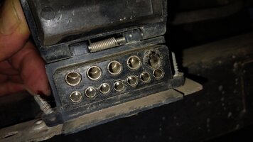
Here's a pic of one that had a meltdown, it was fitted with flap at the top so the flap was holding it in place but still allows movement of the big pins with the smll pins held firmly by the cable weight, reversed the flap and capable firmly hold it ll down, case closed.


IMG_20250106_143409.jpg
 
Last edited:

Boots in Action

Well-Known Member
Mar 13, 2017
2,096
1,842
113
Ferny Grove, Queensland
They seem to be mostly fitted so the plug has the flap to drop down, whereby the big pins are on the lower level and are locked in place by the flap locking on the lugs and the weight of the cable hold sit down when the other way there is still movement .... I too couldn't see why some had meltdowns until it happened to me and subsequent maintenance on others I found they were all top mounted, hence my view to the cause, I prefer to eliminate all possible causes of failure, this is one of them, only has to happen once to become an issue ................................... I don't like and won't use 12 pins anymore anyway, much prefer the less expensive 7 pin with andersons for high loads ... I ran for many years with the fridge running on a 12 pin no dramas, until it did then I rectified it so never happen again .........
Here's a pic of one that had a meltdown, it was fitted with flap at the top so the flap was holding it in place but still allows movement of the big pins with the smll pins held firmly by the cable weight, reversed the flap and capable firmly hold it ll down, case closed.


PS: @Boots in Action have a look back over your posts, seem to be stuttering a few times ... this sentence will self destruct in 20 hrs.......... weve talked about this before I seem to recall....

View attachment 69926
Fair comment Ian. I believe that fitting with the flap closing downwards would seem to be the better better way to protect the connector sockets from dirt and water intrusion than having the flap below, That would not be as effective in keeping rain and splash water ingress when not connected to cabling. Seems sensible to design it that way?? Or is it easier for some to fit plug by lifting cover rather than pulling down cover to insert plug?? I prefer to have the locking pieces at the top under load by the cable weight rather than having the locking underneath where less load to maintain connector tightness.

Seems we still disagree, but that's life. To each his own. Dirty sockets and loose pins are mainly the cause metal connections cause burnt/melted connectors, regardless of how locked together. So keep them clean and free from water ingress.
 
Last edited:
  • Like
Reactions: Drover

Drover

Well-Known Member
Nov 7, 2013
12,938
19,701
113
QLD
Weird I now get Gedi's 2nd post appearing where it wasn't before and @Boots in Action , Graham I have post 5/6/7 being the same quote from you, ..............

The pic I threw up is the way I don't like them mounted but each to their own though they are more often mounted the other way with the label right way up and hinged at the bottom where the flange on top keeps the water and dust out and it shouldn't weep thru the hinge point, well I assume thats how they designed it, doesn't work that great keeping crap out ................................ I thought last time you thru up a pic of yours it was mounted with the flap hinge at the bottom ??

@Gedi , If the van has reverse lights then wire the tug plug for them if not best to leave it empty ... Your pretty much okay using the big pins for whatever you want, I have even piggy backed the the pin 3 to pin 10 as was easier to consolidate the earth but follow the 7 pin lay out on tug and van in the standard Narva lay out then your compatable with other vehicles, god forbid a tow truck, when I got towed a few years back the towie was all smiles when he found I kept to the standard and didn't change things, he noted many do and causes many hassles in rewiring on side of road, sometimes he even has to run his own set to hang off back of van ...................

You will find variations of van layouts due to seperate runs for fridges and ESC, inclusions for Breaksafe wiring as well, though new van Breaksafe set ups can now be charged from the van battery and don't need to be charged from the tug .... We have even come across identical vans having slight changes in wiring so always check the actual set up, saves fuses...................

I say Narva lay out as its the most often found diagram when looking, as it's an easy way to ID things ..........
 
Last edited:

Gedi

New Member
Jan 4, 2025
3
2
3
Victoria
Weird I now get Gedi's 2nd post appearing where it wasn't before and @Boots in Action , Graham I have post 5/6/7 being the same quote from you, ..............

The pic I threw up is the way I don't like them mounted but each to their own though they are more often mounted the other way where the flange keeps the water and dust out and it doesn't weep thru the hinge point, well I assume thats how they designed it, doesn't work that great I fear ................................ I thought last time you thru up a pic of yours and it was mounted with the flap hinge at the bottom ??

@Gedi , If the van has reverse lights then wire the tug plug for them if not best to leave it empty ... Your pretty much okay using the big pins for whatever you want, I have even piggy backed the the pin 3 to pin 10 as was easier to consolidate the earth but follow the 7 pin lay out on tug and van in the standard Narva lay out then your compatable with other vehicles, god forbid a tow truck, when I got towed a few years back the towie was all smiles when he found I kept to the standard and didn't change things, he noted many do and causes many hassles in rewiring on side of road, sometimes he even has to run his own set to hang off back of van ...................

You will find variations of van layouts due to seperate runs for fridges and ESC, inclusions for Breaksafe wiring as well, though new van Breaksafe set ups can now be charged from the van battery and don't need to be charged from the tug .... We have even come across identical vans having slight changes in wiring so always check the actual set up, saves fuses...................

I say Narva lay out as its the most often found diagram when looking, as it's an easy way to ID things ..........
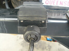
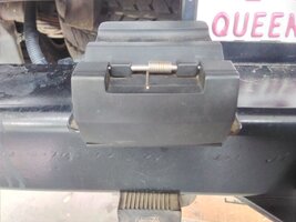
My socket is firmly screwed to the bottom of the tow bar square section which is behind the "back panel" sheet metal and behind the plastic rear bumper. The socket itself is just underneath (2004 Falcon RTV ute). Here is a location photo before I changed the towbar to HD and rewired the socket to add the brake controller wire.
1736210111523.jpeg

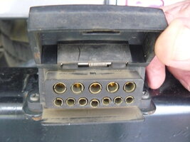
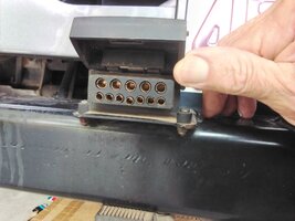
The hinge has to be on the bottom, in this case, which also puts the large pins/ sockets on the bottom. I thought this location, and the flap on the bottom, would reduce the water and dirt ingress but when I pulled the socket apart to wire in the the brake controller, it was absolutely full of very fine dust! This had gotten in past the triangular plastic sleeve cover at the rear, shown in the photo, which had pulled away from the flange on the back of the socket housing. There was no evidence of corrosion, and it had always worked perfectly (on the 7 pin camping trailer I have at least) so I cleaned it out, refitted the plastic back cover/ sleeve properley and it looks completely sealed now.
12 pin socket disassembled.jpg

As I like compatibility too, I will leave the socket wiring with the Narva/ ADR "standard", including the reverse lights and the pink high current wire on pin 9 for "Aux" power (Fridge). Pin 10 and 3 are already bridged/ piggy backed just behind the socket and go to the rear chassis ground point. This was standard Ford Falcon factory wiring in 2004. If I decide I need to run power to the aux on the battery/ BMS input in the van I will run an Anderson circuit from the front of the car. My Fridge is 15A as is the BMS to charge the battery so they shouldn't be too taxing. If the high current pins 9 or 10 get cooked I will run 2 lines with Anderson connectors (one using the pink wire from pin 9 and one new one from the battery. Both negatives will go to the rear chassis ground point, one existing and one new. The pink one is already protected with a 30A fuse and the new line will also be capable of 30A and use a new 30A fuse. I will have to add a voltage sensitive relay or fridge switch to both circuits too.
 
  • Like
Reactions: Drover

Drover

Well-Known Member
Nov 7, 2013
12,938
19,701
113
QLD
Thats the way about 98% of plugs are mounted and the name is right way up so probably how they are designed, pity they haven't found a way to seal them.... The internal state of your plug is about normal, biggest problem is always moisture wicks up the leads and corrodes them slowly, about the only way to stop it is to encase in silicon which may keep moisture at bay but creates other problems, trust me on that and one bit of moisture gets in and rots the wire anyway, I leave it all naked now ................. I reckon your on top of it all ........................

If you use the current cables onto andersons later on get andersons with the pins to suit the cable makes for a better join, many opinions about solder or crimp, I solder as repairs out bush are so much simpler............ I have used chassis earth often, on proper chassis and haven't had any problems but they have been on good connections usually a welded bolt and the same rail that the battery earth is bolted to....................... I don't have the ability to charge from my tug, as I camp for weeks on end off grid relying entirely on solar so saw no need to bother with charging from tug, in fact I don't even charge from the mains, been that way for a number of years and haven't been caught out yet, even with days of thick cloud but I do have a Honda handy... if it was that miserable long enough to not get any charge we would probably leave the area anyway before the river came up. ...............
 
Last edited:
  • Like
Reactions: jazzeddie1234